Do-it-yourself circular: drawings, video, description. How to make a circular saw with your own hands How to make a homemade circular saw shaft
It is difficult to imagine a carpentry workshop without a circular saw, since the most basic and common operation is the longitudinal sawing of workpieces. How to make a homemade circular saw will be discussed in this article.
Introduction
The machine consists of three main structural elements:
- base;
- sawing table;
- parallel stop.
The base and the sawing table itself are not very complex structural elements. Their design is obvious and not so complicated. Therefore, in this article we will consider the most complex element - the parallel emphasis.

So, the parallel stop is the movable part of the machine, which is the guide for the workpiece and it is along it that the workpiece moves. Accordingly, the quality of the cut depends on the parallel stop, because if the stop is not parallel, then either the workpiece or the saw curve may jam.
In addition, the rip fence of a circular saw must be of a fairly rigid construction, as the artisan exerts force by pressing the workpiece against the fence, and if the fence is allowed to move, this will lead to non-parallelism with the consequences indicated above.

There are various designs of parallel stops, depending on the methods of its attachment to the circular table. Here is a table with the characteristics of these options.
| Rip fence design | Advantages and disadvantages |
| Two-point attachment (front and back) | Advantages:· Pretty rigid construction · Allows you to place the stop in any place of the circular table (to the left or right of the saw blade); Does not require the massiveness of the guide itself Flaw:· For fastening, the master needs to clamp one end in front of the machine, and also go around the machine around and fix the opposite end of the stop. This is very inconvenient when selecting the required position of the stop and is a significant drawback with frequent readjustment. |
| Single point attachment (front) | Advantages:· Less rigid construction than when fixing the fence in two points · Allows you to place the fence in any place of the circular table (to the left or right of the saw blade); · To change the position of the stop, it is enough to fix it on one side of the machine, where the master is located during the sawing process. Flaw:· The design of the stop must be massive in order to provide the necessary rigidity of the structure. |
| Fastening in the groove of the circular table | Advantages:· Fast changeover. Flaw:· The complexity of the design, · The weakening of the design of the circular table, · The fixed position from the line of the saw blade, · Quite a complex design for self-manufacturing, especially from wood (made only from metal). |
In this article, we will analyze the option of creating a design of a parallel stop for a circular with one attachment point.
Preparation for work
Before starting work, it is necessary to determine the necessary set of tools and materials that will be needed in the process.
The following tools will be used for work:
- Circular saw or can be used.
- Screwdriver.
- Bulgarian (Angle grinder).
- Hand tools: hammer, pencil, square.
In the process, you will also need the following materials:
- Plywood.
- Massive pine.
- Steel tube with an inner diameter of 6-10 mm.
- Steel rod with an outer diameter of 6-10 mm.
- Two washers with an increased area and an inner diameter of 6-10 mm.
- Self-tapping screws.
- Joiner's glue.
The design of the stop of the circular machine
The whole structure consists of two main parts - longitudinal and transverse (meaning - relative to the plane of the saw blade). Each of these parts is rigidly connected to the other and is a complex structure that includes a set of parts.


The pressing force is large enough to ensure structural strength and securely fix the entire rip fence.

From a different angle.

The general composition of all parts is as follows:
- The base of the transverse part;
- Longitudinal part
- , 2 pcs.);
- The base of the longitudinal part;
- clamp
- Cam handle
Making a circular
Preparation of blanks

A couple of things to note:
- planar longitudinal elements are made from, and not from solid pine, like other parts.


At 22 mm, we drill a hole in the end for the handle.

It is better to do this with drilling, but you can just fill it with a nail.

In the circular saw used for work, a home-made movable carriage is used from (or, as an option, a false table can be made “in haste”), which is not very a pity to deform or spoil. We drive a nail into this carriage in the marked place and bite off the hat.


As a result, we get an even cylindrical workpiece, which must be processed with a belt or eccentric grinder.

We make the handle - this is a cylinder with a diameter of 22 mm and a length of 120-200 mm. Then we glue it into the eccentric.

Cross section of the guide
We proceed to the manufacture of the transverse part of the guide. It consists, as mentioned above, of the following details:
- The base of the transverse part;
- Upper transverse clamping bar (with oblique end);
- Lower transverse clamping bar (with oblique end);
- End (fixing) bar of the transverse part.
Upper cross clamp
Both clamping bars - upper and lower have one end not straight 90º, but inclined ("oblique") with an angle of 26.5º (to be precise, 63.5º). We have already observed these angles when sawing blanks.

The upper transverse clamping bar is used to move along the base and further fix the guide by pressing it against the lower transverse clamping bar. It is assembled from two blanks.


Both clamping bars are ready. It is necessary to check the smoothness of the move and remove all defects that prevent smooth sliding, in addition, it is necessary to check the tightness of the inclined edges; gaps and cracks should not be.
With a snug fit, the strength of the connection (fixing the guide) will be maximum.

Assembly of the transverse whole part


Longitudinal part of the guide
The entire longitudinal part consists of:
- , 2 pcs.);
- The base of the longitudinal part.
This element is made from the fact that the surface is laminated and smoother - this reduces friction (improves sliding), as well as denser and stronger - more durable.

At the stage of forming the blanks, we have already sawed them to size, it remains only to ennoble the edges. This is done with edging tape.

The edging technology is simple (you can even glue it with an iron!) And understandable.
The base of the longitudinal part


And also additionally fix with self-tapping screws. Do not forget to observe the 90º angle between the longitudinal and vertical elements.

Assembly of the transverse and longitudinal parts.


Right here VERY!!! it is important to observe the angle of 90º, since the parallelism of the guide with the plane of the saw blade will depend on it.


Installation of the eccentric


Guide rail installation
It's time to fix our entire structure on a circular machine. To do this, you need to attach the bar of the transverse stop to the circular table. Fastening, as elsewhere, is carried out with glue and self-tapping screws.


... and we consider the work finished - the do-it-yourself circular saw is ready.
Video
The video on which this material was made.
First, let me tell you about my hobby. I like to make things: to create with my own hands the things necessary in the house that increase comfort and decorate the home. I especially like working with wood - carpentry, carpentry. The desire to have an "assistant" in its use that speeds up work and improves its quality served as the main motive for creating the presented combined machine for producing joinery blanks, or, one might say, a woodworking mini-complex.
My practical, albeit limited, experience with industrial machines, both woodworking and metal-cutting, turned out to be very useful in the design and manufacture of this mini-complex. Now with its help it is possible to produce a variety of processing: sawing (both in the longitudinal and transverse directions of the fibers); planing; grinding and polishing, turning and drilling (and you never know what else - it's hard to list everything) wood products, and some operations even from metal.
The mini-complex consists of two, in general, independent, machines (except that the first serves as a base or support for the second). The first is a circular saw with an electric jointer. The second is a lathe-drilling machine.
Today we will talk about the first. Consider its device in more detail. But first of all, I note that it was designed, so to speak, according to the aggregate scheme (the jointer knives and the circular saw have a common drive and are fixed on one working shaft - the rotor). This decision allowed me to make the design simpler and more technological, which undoubtedly affected the rational placement of the main components and assemblies. This machine has components both industrially manufactured and ordered by professionals and, of course, made by one's own hands. There are even unusual details, for example, the supporting part of the machine - the frame, is nothing more than "legs" from an old sewing machine. And she successfully fit into the overall design with virtually no alterations, or rather, the width of the planer table was adjusted to its appropriate size. The main parts of the bed (side rails, crossbars, spacers) were made from channel No. 5. Both designs: frame and bed are welded.
The three-knife rotor installed on the machine with double-sided (double-edged) jointer knives, saw blades with carbide tips, and various kinds of devices make it possible to obtain high-quality lumber products. In planing (planing) mode, the width of the machined surface is 260 mm, and the depth of cut is up to 2 mm.
Jointer and circular saw drive
Tables (inlet and outlet) jointer and control panel (in the foreground)
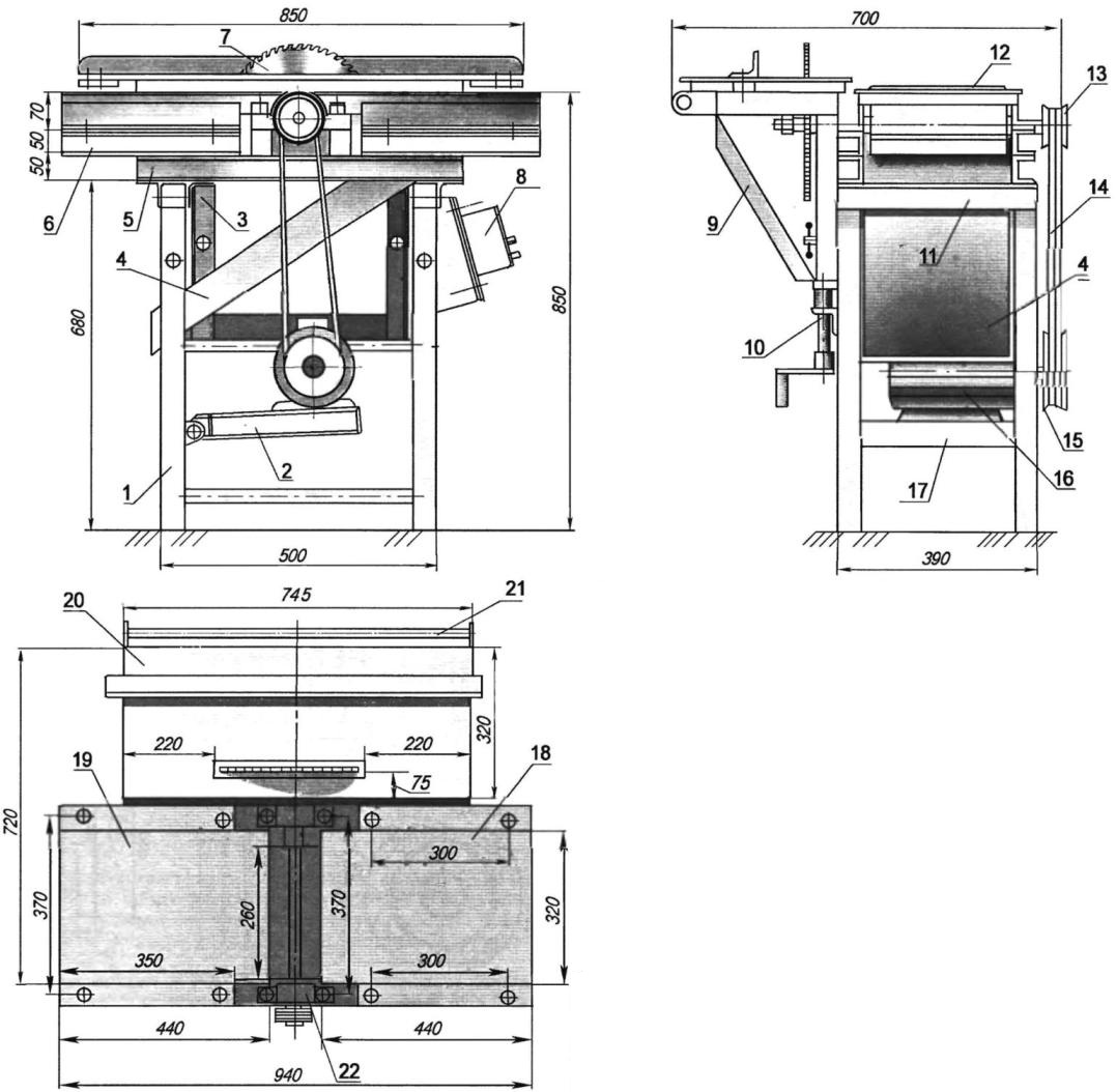
Woodworking jointer and "circular" (click to enlarge): 1 - frame (from a foot sewing machine, stamped steel channel 50x50x50, 4 pcs.; 2 - hinged sub-engine platform; 3 - additional frame stand for mounting the "circular" lifting table "(corner 50x50, 2 pcs.; 4 - tray (duralumin sheet s1.5); 5 - longitudinal side (rolling channel No. 5.2 pcs.; 6 - under-table remote substrate (rolling channel No. 5, 4 pcs.; 7 - circular saw (Ø300x32); 8 - control panel; 9 - subframe of the "circular" lifting table (corner No. 5); 10 - mechanism for lifting the "circular" table (jack); 11 - transverse drawer (rolling channel No. 5, 2 pcs. .; 12 - jointer; 13 - driven pulley; 14 - V-belt (2 pcs.; 15 - V-belt drive pulley; 16 - electric motor (N=3 kW, n=1500 rpm, U=380 V); 17 - cross connection (steel profile, 4 pcs.; 18 - jointer discharge table; 19 - planer intake table; 20 - "circular" lifting table; 21 - guide trimming facilities (pipe Ø17); 22 - bearing housing of the working shaft (2 pcs
The rotor (or working shaft) is the most important, complex and critical part of the machine. In addition, it is common to jointer and circular. I made it (or rather, I ordered a turner, and then a milling machine) according to the drawings published in the article "Small, yes universal" by V. Avtukh from the Belarusian city of Grodno in the magazine "Modeler-Constructor" No. 11 for 2003. But since this detail is very important, and the publication was quite a long time ago, I will give the drawing of the rotor again, especially since I made some changes to it: for example, I lengthened the knives, and, accordingly, the rotor, seats (trunnions) for other bearings, etc. d.
In the same issue of the magazine, I "peeped" the lifting mechanism of the "circular" table - by adjusting its height on the machine, replacing the circular saw with a suitable cutter (or with the same saw in one or more passes), you can select grooves, "quarters" and folds different sizes.
The saw blade has a diameter of 300 mm and allows for a maximum cutting height (or groove depth) of up to 80 mm in one pass. Cutting the edges of the board at different angles is helped by a device mounted on the edge of the desktop of a circular saw. This sliding mechanism (I'll call it a sled) is very convenient when processing the end edges of the board.
The reliability of this machine was tested in the process of creating another machine - a lathe. Working on its bed, for three hours in a row I cut longitudinal guide oblong holes (grooves) on the upper shelves of its channels using cutting wheels installed in place of the saw blade, and then polished them.

Jointer table: 1 - longitudinal element of the strapping (corner 45x45, 2 pcs.; 2 - rear strapping element (corner 45x45); 3 - front strapping element (corner 45x45); 4 - table top (steel sheet s5)

Under-engine platform frame: 1 - longitudinal piping element (stamped steel channel No. 5, 2 pcs.; 2 - transverse piping element (stamped steel channel No. 5.2 pcs.; 3 - frame suspension eye (steel sheet s5, 2 pcs.; 4 - frame cross link; 5 - cross link eye (steel sheet s5, 2 pcs.; 6 - frame suspension axis (steel, circle 20); 7 - cotter pin

Jointer and circular saw rotor (click to enlarge): 1 - M8 screw with spring washer; 2 - pressure washer O35x25 (steel, sheet s4); 3 - driven two-strand pulley; 4 - bearing housing cover (2 pcs.; 5-bearing 18037 (2 pcs.; 6 - bearing housing (2 pcs.; 7 - rotor (steel 45); 8 - thrust washer; 9 - saw blade; 10 clamping washer; 11 - nut M20; 12-clamping plate of the knife (3 pcs.; 13-joiner knife, 3 pcs.; 14 - spacer (M6 screw, 12 pcs.

Circular saw lifting table with workpiece trimming mechanism
In the middle of the frame (half the length), a working shaft is installed, the bearing units of which are fixed to it with M20x1.5 bolts 70 mm long. The shaft is driven from the left side. If you look from the side of the worker's place, then the left side is the knife part of the planer head. On the right side there is a shaft neck with a diameter of 32 mm. Depending on the operation performed, it can be equipped with: a circular saw, a milling cutter, an emery, grinding or cutting wheel. Important! The tool mounting nut on the shaft has a right-hand thread. The working surface of the machine is formed from three steel plates (tables). Two plates are located on the sides of the planing rotor (shaft). The first is the receiving table, located closer to the carpenter, the second table is the outgoing one. Both tables are the same size. There is no special mechanism for adjusting the height relative to the cutting tool at the retracting table, and this operation is carried out as necessary with the help of steel spacers.
Table tops are made of 5 mm thick steel sheet in the form of inverted trays (or gutters) mounted in frames of 45x45 angles and welded to them.
The table of a circular saw, on the contrary, can be easily adjusted in height relative to the saw blade during operation using the built-in lifting mechanism. On the right side of the "circular" table, on a longitudinal guide, there is a mechanism with an angle setting scale, with which you can trim the ends of the boards, not only at a right angle, but also at any other angle. This mechanism is based on the corresponding device for a hand saw.
I note that the described device is easily removed: removed or lowered down. The longitudinal guide is made of a steel pipe with a diameter of 17 mm, it is fastened with the help of eye brackets on the edges of the table of a circular saw.
On the same side of the same table, by means of clamping bars, a guide bar made of a steel rolling angle 50x50 mm is attached to the table with M10 bolts. The distance between the saw blade and the bar determines the width of the workpiece to be cut. And the bar itself helps to maintain a given width along the entire length of the workpiece without marking the latter.

The lifting mechanism of the "circular" table and fastening to the table of the guide bar (click to enlarge): 1 - frame, 2 - thrust cross member of the frame (corner 50x50); 3 - jack (M20x2 screw); 4 - thrust cross member of the lifting table (corner 45x45); 5 - lifting table stopper (special screw M12x1.5.2 pcs.; 6 - circular saw; 7 - guide bar; 8 - drawer side (40x40 corner, 4 pcs.; 9 - lifting table stand (40x40 corner, 2 pcs.; 10 - strut (corner 40x40, 2 pcs.; 11 - tabletop; 12 - additional frame stand; 13 - clamping bar (steel, 2 pcs.; 14 - semi-stud-locker with M10 nut (2 sets; 15 - special screw M10, 2 pcs
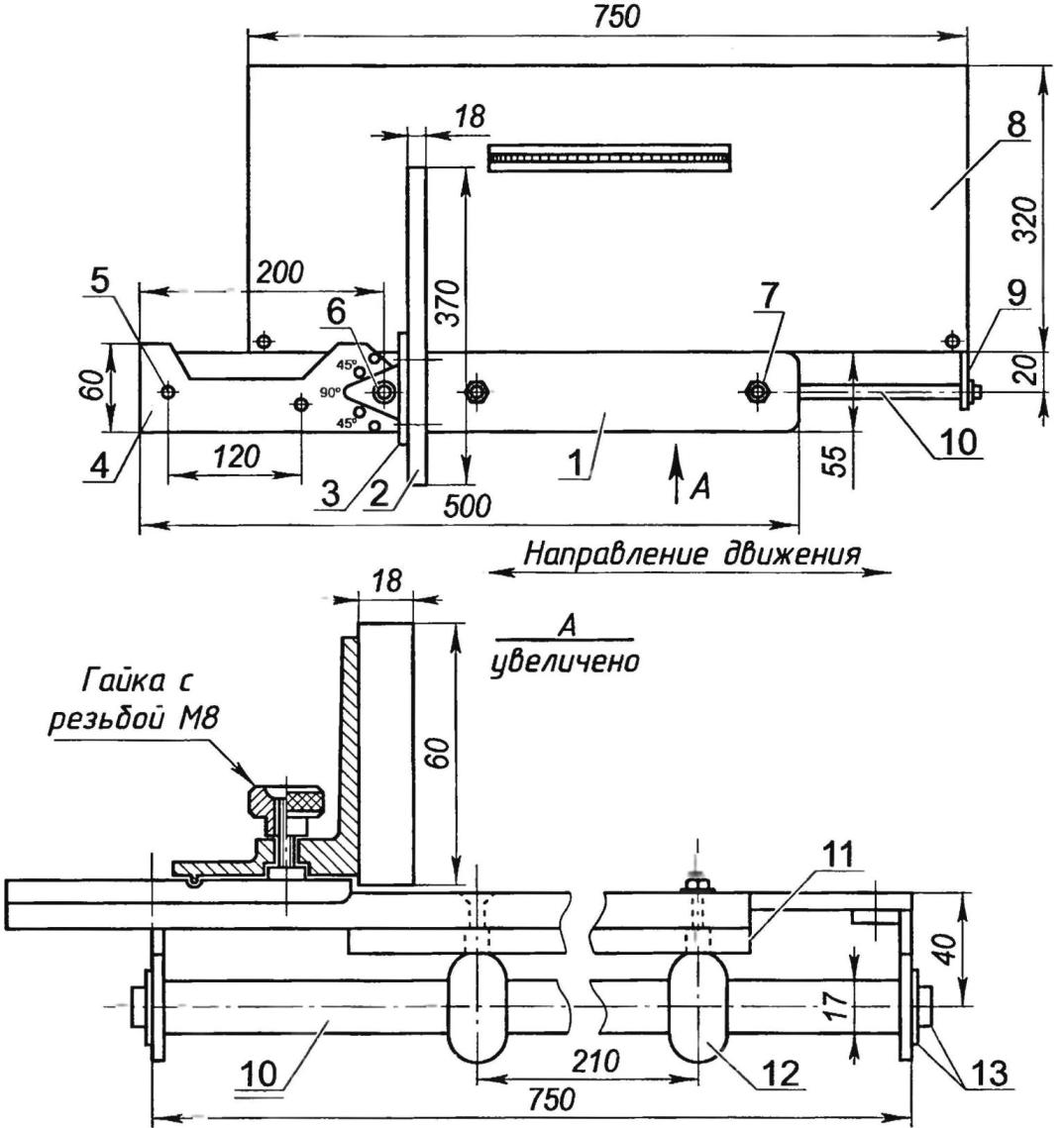
Mechanism for trimming blanks (details pos. 3,4,6 are used from a hand saw) (click to enlarge): 1 - base (board s15); 2 - emphasis (board s18); 3 - stand (steel); 4 - plate with a scale (steel); 5 - fixing the plate to the base (M8 bolt, 2 pcs.; 6 - stopper (special knurled nut M8); 7 - fastening the bushings to the base (M8 nut, 2 pcs.; 8 - lifting table "circular"; 9 - bracket fastening the guide to the table (steel sheet s5, 2 pcs.; 10 - guide rod (pipe Ø17); 11 - backing plate (steel, sheet s5); 12 - bushing (steel, 2 pcs.; 13 - fastening the guide rod (screw M12, 2 pcs
The rotor drive - the working (tool) shaft - is carried out by a two-strand V-belt transmission (although in practice I use only one belt) from a three-phase (380 V) 3 kW electric motor with a rotation speed of 1500 rpm. The engine is located at the very bottom inside the frame and is hinged on a suspended cantilever subframe, which made it possible to solve the problem of belt tension without an additional roller. To ensure high-quality processing of the material, the speed of the working shaft was increased due to the accelerating V-belt transmission. At the drive, the diameter of the motor pulley is one and a half times larger than the diameter of the working shaft pulley, therefore, the knife rotor and the circular saw rotate at an angular speed of about 2250 rpm. The electric motor is powered through a four-wire cable, the wiring is made in accordance with all safety standards, the frame is grounded. In the event of a short circuit or overload, the starting machine is able to almost instantly turn off the power in automatic mode. After work, the machine should be de-energized, cleaned of sawdust and dust.
The machine has been in operation for six years. I carry out routine maintenance: I inject bearing assemblies, check the serviceability of fastening the jointer knives, the condition of the teeth of the saw blade, inspect the drive V-belts and power cables of the machine.
It would not be superfluous to recall that the machine belongs to the mechanisms of increased danger. Rotating parts and unused cutting tools must be covered with fixed covers. Working on the machine requires the utmost concentration of attention, compliance with safety regulations. Do not rush, do not apply force to speed up the process, work for your own pleasure. The carpenter's workplace should be well lit, the space around the machine should be sufficiently free, and the floor covering should not be slippery.
When high precision and cleanliness of processing are not required when trimming and dissolving blanks, this simple and lightweight machine can successfully replace bulky and heavy industrial machines.Its main advantage is that for the manufacture of the machine you will have to make only a few simple parts. And you can assemble the machine from finished parts in just a few minutes. As a bed for it, you can use any workbench or an ordinary wooden table.
 The assembled sawing machine is shown schematically in Fig. 1. An obvious plus of the design is the absence of a belt drive. The disc drive shaft is directly connected to the motor shaft extension. To do this, a hole Ø22 mm and a depth of -70 mm was drilled at one end of the drive shaft, into which the engine shaft extension during assembly is included. The rigid joint of the shafts is ensured by a through locking screw M8 (see Fig. 1).
The second end of the drive shaft is supported by bearing #204. A neck Ø20 mm is machined under it at the end of the shaft. This journal must be sized to allow a sliding fit of the bearing. In order not to complicate the design of the thrust bearing housing with special covers and anthers, I took the latter in a closed (dustproof) version.
 The saw blade is mounted on the machine shaft as usual - with the help of two flanges and a nut, the dimensions of which for blades with a bore diameter of 32 mm are shown in fig. 2. Please note that in order to prevent spontaneous unscrewing of the nut during operation, the thread here must be left-handed. To hold the drive shaft while tightening the fixing nut, a Ø10 mm through hole is drilled in it (see Fig. 2).
 As a drive for my machine, I use an asynchronous three-phase electric motor with a power of
2.2 kW ("three-thousander"). I turn it into a single-phase network through phase-shifting capacitors.
I determined the total capacity of the battery of these capacitors from the ratio - 66 microfarads per 1 kW of engine power. This relation has been obtained in a purely practical way. I have never tested it with formulas, but I think they will give about the same value.
When assembling the machine on a workbench, I install the engine so that it is to the right of the worker. The saw table must be at a height of approximately 85 cm from the floor.
And, of course, in no case should we forget about safety: a saw blade guard, engine grounding and reliable insulation of electrical cables are a must.
S. Tyulyumdzhiev,
According to the materials of the magazine "Do it yourself"
- In the woodworking industry, in conditions of mass production, as a rule, special (operational) high-performance machines are used, configured for the continuous production of the same type
- A feature of this design of a jigsaw driven by a sewing machine engine is the presence of a simple dust collector that ensures continuous removal of sawdust. Using the Foot Control
- The lack of light on the site is a misfortune known to many summer residents. It is especially annoying if the electricity is cut off in the spring or summer at the hottest moment of construction work, when every day is expensive and
- I got the woodworking machine without an engine, fasteners for it and other components. Having bought an electric motor, I made a mount in the form of a frame from a corner .. I machined it on its longitudinal slats
- I like to dig into my Voskhod motorcycle, which I bought a few years ago. One bad thing - some nodes are difficult to repair. For example, to replace an oil seal or bearing on a crankshaft with
Content:
Circular type machines belong to the class of specialized processing mechanisms, without which no well-equipped home workshop can do.
This sample of woodworking equipment is especially relevant in the conditions of a country house and a summer cottage.
When evaluating the possibilities of purchasing ready-made equipment, you will encounter a number of problems related to the inconvenience of handling cheap stand-alone circular saws and the too high cost of professional processing equipment.
The only correct approach to solving this problem is to make a circular machine with your own hands, using materials and equipment that are commercially available.
Note! In order to save money in small-sized models of machine tools, an autonomous circular saw is most often used as a cutting tool, which is rigidly mounted on the bed.
With the help of a home-made machine, you can saw boards, plan a slab, and also make bars of the section you need.
If desired, it will be possible to significantly expand the functionality of your product by providing it with the possibility of processing wood using an electric planer.
Design requirements
Before starting work, it will be necessary to prepare a small sketch, which should indicate not only the location of all the structural elements of the future machine, but also their main dimensions. When drawing such a sketch, it should be taken into account that your circular machine may consist of the following functional units:
- bed, which serves as the basis of the entire product;
- countertops with an industrial model of a hand-held circular saw installed on it;
- remote control panel for turning on and off the actuator (circular saw).
Small Tabletop Circular Machine
The specified composition of the machine is typical for small-sized products on a wooden frame. For capital equipment manufactured on the basis of metal profiles (corners), its scheme has a slightly different look. The composition of such a product should include the following elements:
- a base made of steel frames and brackets on which a shaft with a drive pulley is mounted in bearing pairs;
- a tabletop with slots for the processing blade, mounted on top of a metal frame and rigidly fixed to it;
- a set of special drive electrical equipment located in the lower part of the frame and providing the required functionality of the device (it includes an electric motor, a starting device and a transformer-converter).
The main requirement for any type of bed is to ensure maximum reliability and stability of the structure. As options for the execution of the machine base, we will consider both frames made of metal profiles (corners) and load-bearing structures made of wood.
When familiarizing yourself with the requirements for the electrical equipment of a home-made machine, first of all, you should decide on the power of the drive of the cutting tool (or autonomous saw), which for domestic conditions should not exceed 850 watts.

Stationary circular machine
In addition, before preparing a sketch of a future product, such technical characteristics of the equipment used as:
- Depth of cut, which sets the allowable thickness of the wood pieces to be processed on your machine. This indicator for industrial samples of woodworking equipment ranges from 5 to 8 cm, which is quite enough for cutting standard boards and thick plywood.
Additional information: In the event that you need to process wood blanks of greater thickness, it is necessary to provide a special lifting mechanism in the bed that allows you to change the position of the disk in height.
- Before manufacturing a capital machine with a separate drive, the operating frequency of the rotor of the electric motor should be taken into account. The choice of this parameter is determined by the lumber processing modes that you most often have to deal with. For simple cutting of wood, this figure can be relatively low, but for a perfectly even (“clean”) cut, you need a higher speed.
Important! Optimal for homemade cutting machines is considered to be a speed that does not exceed the value 4500 rpm. At low engine speeds, the bed can be made on the basis of a reinforced wooden frame, massive enough to prevent mechanism vibrations.
- When drawing up a sketch, ergonomic requirements should also be taken into account, assuming the convenience of controlling the operation of the equipment, as well as the safety of handling it. They relate to the order of the buttons on the operating panel, the restriction of access to the cutting blade, as well as the electrical safety of the drive or individual controls.
After all possible requirements for the future machine are taken into account, you can proceed to its direct assembly.
Frame based on metal profiles (corners)
The upper part of the metal frame is most conveniently made in the form of a rectangular frame 600 by 400 mm, welded from 25 mm corners. Pipe blanks 220 mm long are welded to the four corners of this design (recommended pipe diameter is 17-20 mm).

The bed must ensure the rigidity of the machine
On the frame with the help of bolts, two longitudinal corners are used to fasten the shaft in the bearing cage.
The distance between the corners is determined based on the length of the shaft, and the bearings used for installation are fixed on them with special clamps.
The lower part of the frame of the bed, in order to give it greater stability, is made (welded) from 40 mm metal corners.

Closed type bearing is used to fasten the working shaft
Two jumpers made of the same material are welded across the frame, used to fix the electric motor. There is also a metal platform intended for mounting the launch equipment.

Bearings are attached to the frame with special clamps.
At the corners of the resulting structure, pipe blanks are welded with a length corresponding to the size of the pipes on the upper frame, but with a slightly larger diameter (23-25mm).
Closer to their edge, special clamps (lambs) are used to clamp the lifting pipes of the upper frame, which move when the drive belt is tensioned.
The procedure for assembling the mechanical part of such a machine includes the following operations:
- first, bearings No. 202 are taken and driven onto the working shaft with force;
- after that, a pulley is fixed on the same shaft with an interference fit, previously machined on a lathe and having an inner diameter of the stream of 50 mm;
- then, at the end of the shaft, a thread is cut for the bolt used to clamp the cutting tool (for more reliable fixation, paronite and metal washers can be placed under the bolt);
- upon completion of this part of the work, we proceed to the installation of a drive manufactured on the basis of a three-phase asynchronous motor with a power of 1.5 kW (1500 rpm). A pulley is mounted on the shaft of such an engine, having an internal size of the stream of approximately 80 mm;
- at the next stage of assembling the frame, two finished halves of the frame are connected together (in this case, pipes of smaller diameter are inserted into larger ones);
- at the end of the work, a belt is pulled on the shaft, and then the structure is fixed in this position by means of special “lamb” clamps.
Machine on a wooden frame
The easiest and most affordable way to make a machine bed involves the use of ordinary boards or thick plywood for this purpose. In this version of the design, the actuating unit is placed directly under the table (table top), in which a slot of the appropriate dimensions is made for the cutting blade.

Wooden frame is reliable and easy to manufacture
As an example, we will consider the option of manufacturing a bed with a height of approximately 110 - 120 cm, designed to fix a hand-held circular saw on it. The length of the countertop of this design can be changed within small limits at your discretion.
Note! The height of the structure, if desired, can be adjusted, taking into account the height of the person working on the machine. And if it is necessary to process very long boards on it, the dimensions of the countertop can be increased to the required size. In this case, you will have to worry about mounting additional support legs.
The most convenient material for making countertops is multilayer plywood with a thickness of at least 50 mm. However, other materials can be chosen for these purposes (plexiglass or fiberglass boards, for example). As for such a common material as chipboard, its use in this case is undesirable, as it does not provide sufficient surface strength.
To make a machine on a wooden base, you will need the following materials:
- preparation of sheet iron;
- standard sheet of thick plywood;
- a pair of bars with a section of 50x50 mm;
- thick boards with a standard size of 50 x 100 mm;
- steel corner, necessary to increase the rigidity of the fastening of the guides;
- a circular saw;
- two clamps.
In addition, you will have to stock up on the following set of tools, without which the assembly of the machine is simply impossible:
- classic screwdriver and electric drill;
- a simple hacksaw for wood or a jigsaw;
- measuring instruments (square, tape measure, ruler);
- portable cutter for wood processing.
In the absence of such a cutter, it will be possible to use the help of friends or neighbors who have a milling machine in their household.
Additional Information: Some home crafters prefer to make countertops from end-of-life kitchen tables. However, this design will not be durable, since the source material has been used for a long time in a humid room. That is why it would be wiser to make all structural elements from new blanks, which at the same time will allow you to take into account your personal tastes and preferences.
Countertop manufacturing
Work on the manufacture of this part of the equipment is carried out in the following sequence:
We start by marking a piece of plywood, carried out in such a way that its edges are flush with the edges of the prepared iron sheet. After marking, using a hacksaw or electric jigsaw, you can cut the plywood blank to the required size. If desired, it will be possible to process its edges with a cutter, although this is not at all necessary (the main requirement for this element is its reliability, not attractiveness).
Upon completion of these operations, the surface of the countertop is carefully processed (rubbed) with an emery cloth of medium grit.
Then, on its lower part, the position of the slot for the saw blade is preliminarily marked. To do this, it is necessary to determine the dimensions of the sole prepared for the installation of a circular saw. For the convenience of carrying out measurements, the disk is simply removed from the saw, after which it will be possible to easily determine the dimensions of the seat.

For the convenience of marking the tabletop, the saw blade is removed
Upon completion of its preparation, you should take a circular saw and try it on at the installation site. If necessary, the position of its attachment points is corrected (at the same time, the contours of the slot for the saw blade are specified).
The finished plywood table top is covered with a steel sheet, fastened to it with self-tapping screws. Subsequently, special markings can be applied to the working surface, allowing you to adjust the position of the wood blank during its processing.
Frame assembly
Both transverse and longitudinal bars of the frame, used as stiffeners, are also mounted on the lower plane of the tabletop. In total, four such strips are required:
Two transverse jumpers that do not reach the edge of the tabletop by 7-9 cm on each side.
Two longitudinal bars, the size of which corresponds to the same condition (they should not reach the edges of the countertop by about 7-9 cm).
Taking into account these restrictions, it is necessary to outline the points of fixation of the longitudinal bars and crossbars, in which the latter will be attached to the countertop using self-tapping screws of a suitable size.
When marking points, the outermost of them is selected approximately at a distance of 40-50 mm from the edge of the bar (in this case, the step between them should be about 23-25 cm).
Before the final assembly of the frame, through holes for self-tapping screws are drilled in all component parts (bars and countertop). On the front side, the fastening elements are installed in such a way that their caps are completely hidden in the material.
To increase the strength of the future frame base, the bars adjacent to the countertop are pre-coated with wood glue.
After assembly, the structure is temporarily fixed with clamps, which can be removed after the glue has dried.
Support leg attachment
The legs of the table are made from bars of a suitable section (most often, the same 50x50 mm blanks are used for these purposes). The height of the supports is selected for a specific person, i.e. individually.
This should take into account the fact that it is more convenient to work on a circular machine when the tabletop is at hip level. The shape of the legs before their final installation is finalized, taking into account that they taper towards the supporting part (the area of interfacing with the frame base must exceed the area of \u200b\u200bsupport on the floor).
To increase the rigidity and stability of the structure, steel corners can be used in it, which are pressed in such a way as to provide an additional “strut” of the base. To fix them, special bolts with washers are used, installed with caps outward.
Wiring diagram
In the capital version of the design of the circular machine, an autonomous drive is used, which includes an asynchronous type electric motor, the windings of which are connected to the electrical network according to the triangle scheme.

Connection diagram of an asynchronous motor of a circular machine
To control the operation and ensure automatic start of the electric motor, the circuit provides for a magnetic starter built on the basis of an electronic switch (triac) and a current transformer.
To build a machine control scheme on a wooden frame (an option involving the use of a manual circular saw), it will be enough to duplicate the buttons for turning the mechanism on and off, bringing them out and fixing them on one of the legs of the tabletop
You will learn more about connecting the electric motor of the machine from the video.
Today, quite often you can find homemade circular saws. Do-it-yourself circular can be made if the master has at least minimal skills in working with metal. For the manufacture of the structure, you will also need some devices. All work must be done carefully.
Figure 1. Scheme of a stationary circular saw.
It is advisable to make such a device on your own if any of the following materials are available: pieces of a corner made of steel, a rectangular shaped pipe, an engine or a grinder. If there is no motor, it can be purchased at the construction market.
Manual design of the circular
A manual circular can be easily made with your own hands if a grinder is available. You will need to make the following simple fixtures: a sliding stop and an axial handle.
Required details:
- Metal corner.
- Washers.
- Bolts.
- nuts.
- Strip of metal.
- Bulgarian.
- Metal pipe or rod.
Making an emphasis and preparing the necessary holes

The sliding stop is made from several pieces of a small corner of metal, which are located on both sides of the working element. It is worth noting that the working element is a disc with teeth, which is used instead of an abrasive wheel. The gap on each side should be approximately 3-4 mm. The horizontal edges of the corners will need to be rounded at the bottom so that they do not cling to the workpiece being cut. The corners will need to be cross-linked at the front and back. To do this, it is best to use bolts with nuts, the gap can be made using a package of washers.
On the body of the tool you will need to put on a clamp from a strip of metal. The screw tie of the clamp should be placed at the bottom of the structure. You will need to rigidly fasten a double-folded strip of tin or galvanized steel with a hole for the rear stop bolt to slide. The stop must be fixed at the rear of the structure. The clamp with the rear thrust post can form a single structure, however, the thickness of the metal strip in this case should be approximately 1-1.5 mm. By moving the washers that provide the gap, you can achieve the same gaps between the working element and the side parts of the stop.

In the tool gearbox housing, you will need to drill 2-4 threaded holes for small fasteners. The gearbox will first need to be disassembled and identify places where it is possible to drill. The holes are intended to be able to fix the homemade axial handle. If a standard side handle of a grinder is used, then it will be quite difficult to make an even cut even for a master with extensive experience.
Production of a handle and an adjusting rod
The axial handle is made of a pipe or rod in the form of a horn, which is directed upwards. In this case, a cross brace of a small width can also be used. The ends with which it will be fixed to the gearbox do not need to be splashed. In these parts, you will need to drill holes for fasteners. If the mounting ends splash, the handle will bend from the effort during operation.
If the handle looks like a horn, then its far part must be splashed in a horizontal plane and a hole drilled in it for the axis of 4-5 mm with a margin. If the handle is a bracket, then in the holes that are located in the gearbox, you will need to install a piece of a rod or tube sticking out forward. The end of the element must be splashed and a hole drilled in it. There should be a small distance between the rod and the bracket - approximately 100 mm.

Next, you need to take a piece of steel rod 4-5 mm, which will be used as an adjusting rod. One part of it needs to be bent in the form of a loop, slightly splashed and drilled a hole for the front stop bolt. Substituting the washers on the front of the stop, you need to achieve a uniform slot width along the entire length of the structure. If a 6 mm rod is used, then you will need to prepare several washers of small thickness.
On the back of the rod you need to cut the thread. The element will fit into the hole on the handle. You must first screw one nut onto it, and upon completion of assembly, the second. You will need to loosen and tighten the nuts in turn so that you can adjust the depth of cut. At this stage, the manual circular will be ready for use.
Desktop small circular
A manual circular can be easily converted into a small desktop design.
To do this, you need to make a U-shaped frame from a pipe or rod 15-20 mm and attach a lever. The lower part of the frame must be bent along the cutting direction to horizontal, and then fixed to the table with self-tapping screws. To make the structure stable, you can additionally install slopes.
On the horizontal crossbar you will need to put on a rotating lever from a T-shaped pipe.

The transverse part of the element will need to be cut into two parts. After the structure is installed, the elements will need to be fastened with clamps. To the end of the vertical part with a clamp, you need to pull the hand saw that was made.
A similar design can also be used as a cutting device, for which you need to install a standard cutting wheel in the grinder. However, in this case, the thickness of the cut will not exceed 70-80 mm, everything will depend on the diameter of the working element. In order to be able to process thick lumber, you will need a full-fledged circular saw.
Complete stationary circular
It is possible to make circulars of this type only if you have a design scheme. The difference between a stationary and desktop circular is the height of the bed. A diagram of this type of structure is shown in Fig. one.
The first element to be made is the table. It is covered with tin or galvanized sheet. The wood will rub against the wood or plastic, resulting in a small hole. In this case, it will not be possible to produce a high-quality propyl. The cross joints of the table are made from a metal corner 70-80 mm.
The working element must not protrude more than 1/3 of the diameter above the table base - otherwise the saw will be dangerous. Therefore, if it is necessary to cut a beam of 100 mm, then the diameter of the disk must be 350 mm or more. To drive such a disk, a motor with a power of 1 kW or more is required.
It will be necessary first of all to compare the power of the purchased engine with personal needs. For blanks of 150 mm or more, it is quite difficult to make a circular yourself.
A high-quality adjustable stop can be made from a piece of a corner of 70-80 mm, its length should be 350-400 mm longer than the length of the table. One of the shelves will need to be cut on both sides so that the remainder is equal to the length of the table. The backs need to be bent down. In the lower shelves you will need to drill holes for the threads of the fasteners. After that, you will need to put an emphasis on the table and fix it in the required position with bolts. The stop is set according to the template, which is laid between it and the tool disk.
You will need to use ball bearings that are self-installed. Pins with bearings must be with covers that can protect against sawdust.
It is recommended to use a V-belt drive. The motor comes from an old washing machine. Capacitors can be paper or oil-paper. Other elements will not be able to withstand the reactive power that circulates in the chain.
Making a circular yourself is quite simple if you know the technology and have all the necessary elements available.


